The capacitor buck LED driver circuit uses the capacitive reactance generated by the capacitor with a specific AC number to limit the maximum operating current. For example, at an operating frequency of 50%, a capacitive reactance of approximately 3180Ω occurs with a 1μF capacitor. When an AC voltage of 220 volts is applied to the capacitor, the maximum current flowing through the capacitor is about 70 yen cheaper. However, if the capacitor is an ideal capacitor, the current flowing through the capacitor is an imaginary current, and the work is a low power, so no power is generated in the capacitor (the capacitor belongs to the energy storage component).
According to this feature, when the resistive element is connected in series on the 1 μF capacitor, the voltage obtained across the resistive element and the power dissipation that it generates are completely dependent on the characteristics of the resistive element.
For example, connect a 110V / 8W bulb in series with a 1uF capacitor and connect it to an AC voltage of 220V / 50Hz. The bulb lights up and becomes normal brightness without burning because the 110V / 8W bulb needs 8W / 110V = 72mA. This is consistent with the current limiting characteristics of the 1uF capacitor.
Similarly, if you connect a 65V / 5W cell and a 1uF capacitor in series to a 220V / 50Hz AC, the cell will light without burning, since the operating current of the 65V / 5W cell is also about 70mA. Thus, the capacitor bucking actually uses capacitive reactance current limiting, and the capacitor acts as a limiting current, dynamically distributing the voltage across the capacitor and load.
The traditional way of converting AC power to low voltage DC is to rectify and filter after bucking using a transformer. When limited by factors such as capacity and cost, the easiest and most practical method is to use a capacitor buck power supply.
When switching the circuit, it is necessary to first determine the correct value of the load current and then select the capacity of the step-down capacitor. Capacitor step-down application circuit diagram as shown in the figure below
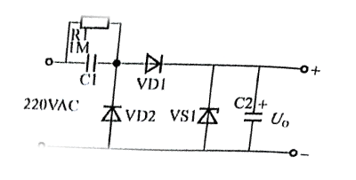
In fact, the charge and discharge current flowing through C1 increases as the charge / discharge current ICC1 flowing through C1 increases and the capacitive reactance XC decreases as the charge / discharge current ICC1 flowing through C1 increases. . If the current Xin Yi is smaller than the charge / discharge current of C1, the maximum capacity current of the zener diode where the excess current flows in the zener Idmax is Ic-like. If it is smaller than X1, then it is necessary to make the selection of the withstand voltage more than twice the power supply voltage in order to operate C1 which makes the zener diode easy to burn. The bleeder resistor R1 needs to be selected to release the C1 charge for the required time.
This article is from Allicdata Electronics Limited.


没有评论:
发表评论