2019年11月15日星期五

Commissioning car controller ST Stellar

    By STMicroelectronics PLS programmable logic simplifies software development and systems support, Stellar automotive microcontroller architecture for this powerful debugging, tracking and testing.
     As the combination of several new technologies on the chip, the chassis and the telephone-assist auxiliary system (ADAS) can be implemented with a power system that is controlled by a personalized microcontroller series "Star". With the six Arm Cortex R52, the first building block generated by the latest microcontrollers is also the core clock frequency of 400 MHz. Together with 16 MB of embedded phase change memory (PCM), it provides high multicore performance for real-time applications.
       Further, Stellar series also has a variety of security and protection features, including a hardware security module (HSM) function and a lock-step. Management software program for the separation and storage protection enhances the security and reliability features.
       The Stellar range meets the stringent requirements of the automotive electronics system ISO 26262 to ASIL-D safety standards. In addition, three floating-point Cortex-M4 cores and DSP extensions act as application-specific accelerators. Due to the long-term close cooperation with STMicroelectronics, PLS has been able to develop optimized debugging and tracking tools for the ST-Partner Program to develop members with the first home from the Stellar to be able to provide this complex automotive microcontroller architecture.
      With multi-core run control, UDE's specific features, you can use the built-in debug logic to synchronize start and stop of all cores or selected groups. Multi-core breakpoints that can be used in shared code simplify the debugging of complex applications. Such a breakpoint is always valid no matter which kernel is currently executing the code. In addition to support for the actual application kernel, UDE also allows debugging of hardware security modules integrated on the Stellar MCU. To this end, HSM can be integrated into multi-core operational control.
The optimized programming of phase change memory (PCM) implemented in the Stellar family of modules is achieved by means of the UDE Memtool flash programming tool integrated in              UDE. Phase change memory allows for faster, safer, and more accurate programming than traditional flash programming. In practice, this means, for example, that even a single byte can be written, whereas only the entire block could have been written before. Due to the nature of the PCM, the over-the-air software (SOTA) for this storage technology can be used particularly efficiently and reliably. The special features of UDE Memtool ensure the smooth support of SOTA.
For detailed analysis of multi-core applications at the system level, the UDE supports a wide range of trace capabilities for the CoreSight debug and trace scheme, where the arm is in the              Cortex-R52-core core of the Cortex-M4, and for the connection to the chip has been achieve.
The family of three devices UAD2pro, UAD2next and UAD3 + PLS universal access devices are also reliably debugged to the stellar microcontroller family via JTAG or arm-specific serial line debug (SWD) interfaces. It is ideal for capturing and storing large amounts of trace data while UAD3+, which is available on the Star MCU with up to 4 GB of trace memory in the special tracking POD for High Speed Serial Trace Port (HSSTP),
2019年11月12日星期二

What is the structure of the LED screen?

      The difference between the LED screen and the OLED screen is not only a letter difference, but the imaging technology of the two is completely different.
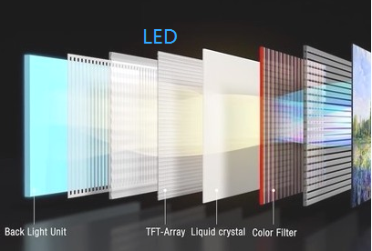
      LED screen structure is more complicated

image.png

       LED screens and OLED screens have fundamental differences in the principle of illumination.
The full name of the LED is a light-emitting diode. Like the traditional semiconductor industry, LED display screens are a way of controlling the display of semiconductor light-emitting diodes. They are usually composed of a plurality of red light-emitting diodes, which are dominated by the display of lights, thereby realizing text, graphics, images, and animation. Display screen for various information such as video and video signals. Its process cost is high. In addition, LEDs can only be used in the form of point sources.
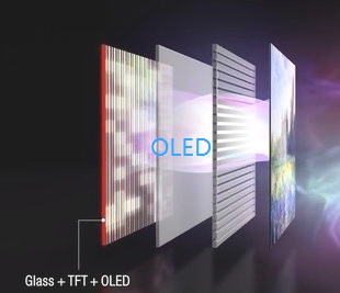
       OLED does not require a backlight, and the structure is lighter and thinner.

image.png 

        The OLED emits light by driving the organic film itself. OLED is a congenital surface light source technology, and the light emitted can be red, green, blue, white and other monochromatic colors, thereby achieving the effect of full color, belonging to a new principle of illumination. The reason why plasma technology, OLED technology and even the image quality of CRT technology in the early years are praised is mainly because they all have the characteristics of "self-illumination".

2019年11月4日星期一

The working principle of the nVIDIA motherboard circuit.

In the mainboard repair encountered nVIDIA motherboard is basically a single bridge, common also ASUS M2N68, M4N78 motherboard.

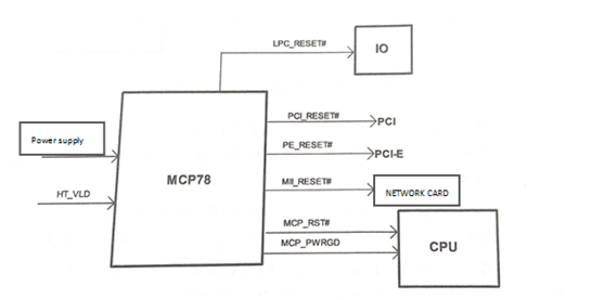
The nVIDIA motherboard automatically generates a clock signal internally after normal power supply and resets when the bridge receives the HT_VLD signal.

The working principle of the reset of the nVIDIA single-bridge MCP78 chipset motherboard is shown in figure 1.

 image.png
Fig. 1 working principle block diagram for reset of nVIDLA single bridge MCP78 chipset motherboard.

1. The main board power-up circuit works, through the power supply circuit step-down to generate memory power supply, bridge power supply, CPU power supply and bus power supply.

2. Bus power supply through circuit conversion to the HT_VLD bus voltage good signal to the bridge, the bridge sends out MCP_PWRGD signal to the CPU, indicated that the main board power supply is normal.

3. The bridge issues the LPC_RESET# reset IO chip, the PCI _ RESET# reset PCI slot, the PE_RESET# reset PCI-E slot, the M11_RESET# reset Nic chip, and finally the MCP_RST reset CPU.

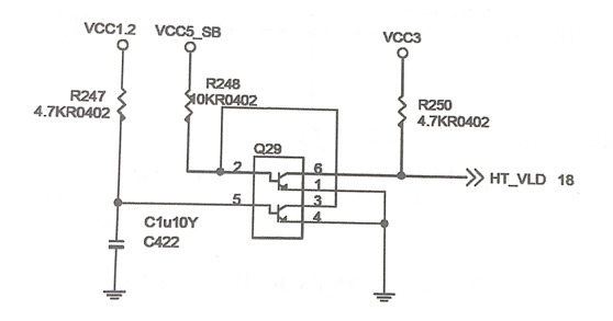
The HT_VLD signal circuit generates power from the VCC 1.2 bus to the 5-pin Q29 via the resistor R247, controls the 3-pin and 4-pin internal Triode on, and lowers the 2-pin voltage so that the 6-pin and 1-pin internal Triode cutoff, The HT_VLD is sent to the bridge via the R250 pull-up for 3.3 V, indicating that the bus is powered properly.
image.png
Fig. 2 HT_VLD signal generation circuit.


This article is from Allicdata Electronics Limited. Reprinted need to indicate the source.


What is the development status and trend of led display?

  Over the past few years, with the further release of the market, the entire LED display industry has regained its vitality, and market com...